Quick Step: How To Place Permanent and Temporary Steps on Open Wire Poles
Some Baby Steps: An Introduction
This will be an easy and enjoyable chapter to write and share with you, as I’ve always appreciated poles with metal steps–since I didn’t possess climbers! As a kid, when no one watched, I scampered up a pole to look at terminals, splices and drop connections where cable was located, getting to touch and feel some pretty interesting stuff. This was one easy way to get close to my favorite equipment and to even open and peer into an NC-25 cabinet, for example, to see what was going on in there!

Typical terminal/junction pole with two NC25 (25 pair protected) terminals, dead-end buck arms and other electronics. Note the placement of steps to insure lineman’s safety as the terminal covers were opened and slid back to expose wiring and not to obstruct further climbs beyond the terminals to the top of the pole.
People have asked whether there was any rhyme or reason to how the pole steps were mounted on utility structures. Was there a pattern to each utility’s use or did the manufacturer of the steps recommend a specific guideline? Power utilities rarely did this on wooden poles–it was a “telephone” or “communications” thing–to place steel steps (although steel towers and occasionally monotube transmission structures have “step bolts”). Note steps only reach to the communications facilities’ level and do not ascend to power secondaries or higher in all but the most exceptional of cases.
Let’s face it; pole steps are an iconic feature of “the telephone pole.” The reason pole steps were used so frequently by railroads and telephone companies was to eliminate climbers’ tearing at habitually visited poles’ surfaces which would inflict severe wear upon them hastening decay. Upon these vital poles hung cross-connect cabinets, large terminals where open wire was terminated to aerial cable or buried cable, carrier equipment equipped with fuses or other “consumables” which compelled periodic climbs by installers, splicers or maintenance personnel.
We might recall the Sunday comic strips’ images of telephone poles with haphazard steps, but actual placement of steps was actually very scientific and quite standardized. The arrangement of stepping correlated closely to the purpose of the pole. Let’s step up and examine this art where it pertained to open wire facilities.
Open Wire Terminal Structures’ Stepping
The termination structure at either end of a toll or exchange lead involved the placement of numerous physical arrangements of wire, termination devices (C-type dead-ends), splices, large varying terminals, bridle wire runs, filters for carrier operation, over-current and over-voltage protection, auto transformers, cable terminations, guy wire attachments and brackets/hardware. Often, major terminus of open wire also included cross-connect boxes, where splicing was was often accomplished repeatedly.
So I visited a number of sites where open wire was once placed and made some notes, photographed and drew some illustrations below on how both permanent and temporary stepping was arranged.
Let’s define the two types of “steps.” Temporary and Permanent.
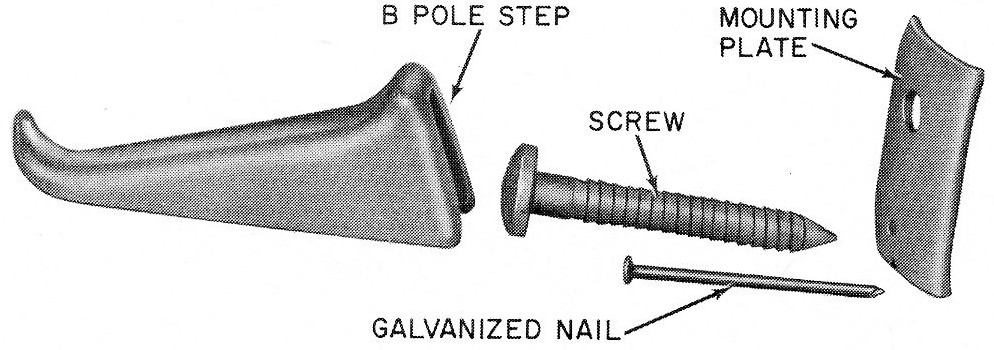
Temporary Pole Step – This was a hardware kit which allowed the installer, splicer or lineman, to bring his own removable step to be slid on the top of an existing lag screw and pole surface mounting plate. The latter were already installed into the pole when originally placed. A galvanized nail was inserted below the lag screw to prevent the plate from moving should it loosen over time. An illustration is shown below of a typical “temporary pole step installation.” The purpose of the “temporary” step was to prevent unauthorized persons from climbing the pole (although that didn’t prevent one of the most infamous unauthorized pole climbs in history: http://cielodrive.com/photo-archive/10050-cielo-drive-telephone-pole.php) Typically, there are two installed on the bottom of the pole.
Here are photographs of the two steps and diagrams incorporating the various parts:


The temporary pole step did not come into significant use until the late 1940s and by the 1950s, it was used considerably. Bucket trucks and other accessible means used by linemen, installers and cable splicers did eventually eliminate their use by the 1980s.
Permanent Pole Step – A single piece of solid circular steel rod, comprising a long lag screw-type pointed end. The rod extends the width of a boot sole with an extension abruptly upturned 90-degrees to prevent the climber’s foot from slipping. About two inches from where the screw form begins is a marking called a “knurled ring”. When inserting and screwing the step into the pole, the marking prevents too much of the step from being lost into the pole surface depth. I’ve placed a picture below to illustrate this simple item.
Below is an American Railway Association 1922 recommendation for pole stepping for a railroad open wire communications and signal pole. Note the differences in step design and placement from their civilian (non-transportation company) counterparts.
Also note the absence of temporary pole steps (they hadn’t been invented yet) and the use of wooden steps attached with long nails (spikes) near the bottom three feet of the pole.

American Railway Association/Communications Section recommended pole stepping for railway signal and communications open wire line structures.
The only restriction to properly stepping a pole was the class, and of course, the amount of length available for the step to be inserted without it poking out the reverse side! While I’ve seen Class 7 poles stepped, most commonly stepped structures were Class 1, 2, 3, 4, and 5. Remember: with much application equipment installed, along with heavy buck arms, open wire poles needed to be sturdy and possess a large circumference.
Below, find an illustration of a typical terminal structure.

Recommended GTE, Bell System and REA/RUS step placement on telecom poles where they were wooden structures. Special steps were engineered for concrete, metal and fiberglass supports in the early 1900s through the present.
The standards I’m covering are universally typical of how AT&T, GTE, the Big Independents, REA/RUS, and railways, placed steps on their poles. There’s no big secret to pole step placing and requirements were virtually the same in all parts of the United States and Canada. Today, poles are climbed much less because of mechanized equipment, bucket trucks and the like, and accordingly, new step installations are rare. However, in tight residential back lots, businesses with restricted heights and widths for vehicles, and hard-to-access locations, stepping poles yet has its many virtues.
Below is a line drawing of two permanent pole steps which were used and recommended by the American Railway Association in the 1920s. The first is essentially a bolt with a rounded head, without a knurl shoulder and self impacting screw end. The second is a permanent type similar to the Bell System, GTE, telephone independents’ use but an early type without the knurled ring shoulder. The shoulder was to eliminate steps being imbedded into the pole too deeply. It was simply a guide to use. All of these steps were usually galvanized steel, although some early types used on other structures were of iron manufacture.