Insulators, Hardware & Other Objects of Interest

This collection can be seen at the Museum of Independent Telephony, Abilene, Kansas.
First . . . Some Comparisons of American, European and Australian Styles
 Assortment of European pin-type porcelain communications insulators, 1940-1960s.

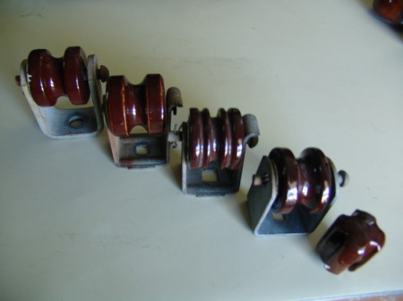
Single and double-petticoated pin-type styles, all European. Danish unit (smallest) on far left; largest MacIntosh white ceramic on far right, used by the British Post Office Communications lines. In between, two central European makes.

Australian Tempered Glass Insulator, 1950s, similar to a test design by AT&T in the 1930s.

Another view of same “Down Under” open wire communications insulator by CCG Corporation

. . . what befell open wire . . .
Insulators, Hardware & Other Items of Interest

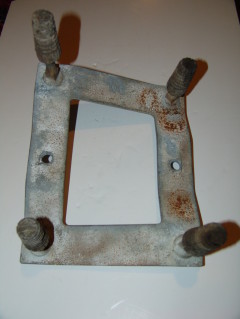
The Alcoa Case Span Bracket for suspended point type transpositions typically placed at river crossings, canyons or wide highway easements.
The subject of “insulators” for telecommunications is such a vast topic that years could be spent enumerating all their qualities, histories, applications, patents, colors, shapes, sizes and characteristics.
Pole line hardware topics, too–even for such simple items as: transposition brackets, braces, bolts, pins, pole steps and the like, comprised a rich complexity of materials, use factors, geographic and governmental standards, terrains, climates and corporate purchasing styles. We will speak about these topics, as our website develops.
While these topics are and have been important factors to many insulator collectors, we’d prefer to cast aside the artistic for a moment and dwelve into the technical side of this topic. Surely, there are insulator collectors out there, who have asked some earching questions. Why do some insulators look the way they do? Why did a specific design gradually change or swiftly morph into a completely different shape? Perhaps you’d like some basic know-how on appraising your collection from the stand point of technological history. So let’s go beyond the unique shapes and pretty colors for a moment and look at the . . . science behind them.
During the first fifty years of their American development, dielectric engineering slowly began to emerge as the most expedient way to produce a consistent product whose enduring quality could extend over a significant lifetime of service to meet expectations of both mechanical and electrical integrity. While supporting an aerial wire 30 feet above the ground took some justified mechanical understanding, other necessities of creating an exceptional insulator, were required to exceed this basic goal.


Engineering-based design was fundamental to the success of operating high quality voice frequency long haul carrier systems. Here, customers’ expectations were high and physical demands upon the system demanding and harsh.
Aside from the common dielectric herd, insulators for telecommunications systems faced problems their electric power breathern did not confront: voice frequency attenuation, wet and dry leakage on high frequency carrier, diverse applications of wire ties, factors of quality differing between steel, iron and wooden pin supports, rifle fire, electrical bonding of pins, radio interference, and other significant issues.
Insulators were not just screwed on steel or wooden pins to support conductors and left merely to their own devices; their use was applied to a unique variety of applications: transposition brackets, dead-end types, span separators, and lengthy bridling wire runs down terminal and junction poles, bushings from apparatus and the like, just to name a few.
Porcelain was also used to a greater extent on American Railway Association/Communications Section designs, where higher voltages for telegraph, signal and special circuit design required them. Both glass and porcelain offered substantial advantages and disadvantages in their use. To discriminate further, manufacturing processes to produce specific glass compounds such as soda lime glass and borocilicate glass called attention to their advantages and disadvantages. The war between wet process vs. dry process porcelain ware use, compounded outside plant engineers’ critical decision-making process. Later fiberglass, Buna Rubber and plastics entered the later scene, offering still more, solutions to critical issues within the open wire era.
So . . . let us investigate the technical side of insulator design for communications by starting with the common nominclature for commercial telecommunications glass insulators during the first quarter of the 20th Century.

Porcelain (Illinois Porcelain) top and soda lime glass (Hemingray) screw-type lead-in insulators for bridling runs. Time period 1940s (top) and 1950s (bottom). Also used by the U. S. Army Signal Corps.

The two DP insulators on the far right and left, fell out of favor because their shallow groove could not properly secure larger conductor sizes. Middle insulator was Pony style used for point type transpositioning and deadends (for single pin use).
The Origins of the Science of Open Wire Insulation Systems
The open wire plant is subjected to considerable stress from all vantage points: mechanical stress, electrical stress and climatological strain. The insulator material chosen in Europe, porcelain typically with a white glaze, for telecom was the direct opposite of what worked most frequently in Canada and the United States: soda lime–and later–tempered, glass.
In the electric transmission and distribution world, the North American application of porcelain for high voltage T&D was contrasted with the use of soda lime glass and some tempered glass for European power system insulation. Why this was the case, is unknown to me. Perhaps it was the expense of glass, or the lack of locally usable clays, business dynamics of bottle manufacturers, but whatever the case, two separate and distinct insulator materials evolved on either side of the Atlantic.
However, we will depart from the European model in this discussion to fully embrace the requirements of the North American continent and communications companies in Canada and the United States.
Much has been written about the lack of quality in early insulator manufacture and the need to establish quality insulating materials. Wood and glass were the dominant types, even back to the first aerial wire telegraph lines in the 1840s. The reader has probably heard the story of how many insulator developers in the communications field–at least the most successful ones–were stimulated in developing suitable insulators because they had been unjustly accused of missing important telegraph messages, when they were at their telegrapher posts.
We will discuss the use of the pin insulator for communications nearly predominantly in this article. There are exceptions. At river crossings and H-fixtures (in the 1900-1930s period, at least) the 6″ diameter brown porcelain Edwin Hewlett “suspension” insulator was applied by Bell and other companies, to dead-end early long span toll and exchange lines. Infrequently, the J.D. porcelain insulator with cemented metal tines was also used in very limited circumstances.
The only other type class of insulator we will digress later at this point, is the clevis or “C-Type” (ANSI brown or grey) dead-end porcelain spool insulator and some variances of the ubiquitous porcelain guy strain insulator. These had specific use for dead-ending open wire only and never used–to my knowledge–for hanging under arms or placed on the top of arms.
In the days of low frequency telegraph and early voice frequency telephone lines, the first modern early generation insulators were considered pretty good. However, as toll leads began to expand beyond towns, cities and into the countryside, many critical limitations began to appear. Once high frequency carrier emerged, then these difficulties were amplified many times over and further development was required.
At low frequencies, leakage current over a glass Pony or Exchange insulator is negligible. These are levels of frequency typically below 3 kHZ. When the first phantommed circuits were strung, the early double-petticoat insulator such as the No. 40 Hemingray (or its earlier predecessor) was sufficient for long distance toll facilities. In 1921, the Hemingray Company introduced an improved version, the No. 42, which had a deep groove, offered substantial improvements in leakage current resistance and could more adequately keep the wooden pin dry immediately underneath the unit.

Australian soda lime AGM open wire side groove pin type insulator.
Base view of the Australian side groove AGM soda lime glass pin type insulator.
Let us at this juncture, make one other critical departure from the world of glass and porcelain to introduce the “shock proof” insulator. These were developed for use in areas where hunters had used glass insulators for target practice, or had been required because the circuits were of such high classification, that they had to be protected at all costs. Continental Rubber Works manufactured a slim little rubber unit with a deep grove, having the highly appreciated ability to screw on a steel pin where the wooden cob had broken or rotted off.
Continental also developed for Western Union, a unit of size similar to that of the Corning-Pyrex “CS” type insulator. No inner petticoat, but a one-inch diameter thimble hole to screw on a standard one-inch pin either of lead or wooden cob design. Several other companies developed purely polycarbonate insulators. H. W. Salsbury, a company well known for hot line cover-up tools and pigs, developed insulators of this type; also the well known electrical manufacturer, (will think of it later), also developed a lightweight clear plastic insulator for railway use in the 1960s.

Shock proof insulators. Clear polycarbonate on far left is H. W. Salsbury; the middle and far right are Continental Rubber Works, Inc. designs.

Top arm porcelain 9-kV pin-type units, ANSI gray and relatively new. Bottom six-pin arm with polycarbonate insulators. Date of line is after 1966.
Shock proof polycarbonate plastic insulators in use on a Burlington-Northern Santa Fe Railway line east of Topeka, Kansas at Westar’s Tecumseh Generating Station. This rail link serves to unload coal for the fossil-fueled plant on the capital city’s outskirts.

A-W polycarbonate SEECO (plastic) black DP shock-proof insulator used extensively by Chicago-Northwestern Railway and others.

Image showing same shock proof design as above with detail of inner petticoat. Insulator of the 1950s.
Essentially, an insulator is of a substance with few free electrons. It is called a “dielectric” and will not allow the free flow of electric energy though its interior. However, electricity can–and will–flow over the surface of an insulator of glass, porcelain, plastic or fiberglass, if the outside is contaminated with dust, mold, dirt or moisture. Some oils and chemicals will also allow leakage over the outside and onto the pin and arm.
Leakage typically exists between the two pins on a crossarm forming a wire “pair.” The sporadic or continuous leakage can be between the defective insulator and wet pin along the wooden crossarm to the other adjoining wet pin and defective insulator. The current flowing between the two pins has two components: one in phase with the potential and one in phase quadrature leading the potential.
What we are mostly concerned with is the energy loss component and most engineers in the telecom field will call this “equivalent conductance.” What is most intriguing about this loss is how it behaves under alternating current conditions vs. direct current conditions.
Let’s take a low voltage power distribution line operating at an alternating current of 2400-volt Delta. When insulators are contaminated, the glaze burned or the body of the unit cracked, the leakage current will occur directly through the insulator material to the wooden or steel pin. Even if the porcelain or glass insulator has physical integrity, let’s say, the dust from a local drought condition would settle upon the outer surface and promote leakage directly over the insulator surface from the line conductor (wire or cable) to the wooden or steel pin. Both these conditions are true of d.c. telephone open wire facilities as well as the a.c. electric power distribution linein our little example.
However, in electric power a.c. transmission and distribution:
Dielectric absorption occurs in insulator material;
Dielectric absorption occurs in the pins supporting the insulator;
Displacement current occurs in crossarms, pins, transposition brackets;
Since there are differences in external resistance of these pins, brackets, and arms, there are further losses due to unbalanced currents;
Finally, there are displaced currents flowing over insulator surfaces, especially typical of differences between steel, aluminum and wooden structures and supports.
After bottle makers and china manufacturers evolved to perfect the “true” insulator and develop standards for them, it was quite clear density of material was a question of quality. Cracks and fractures could not be allowed. The material of glass and porcelain would act as a very good insulator, if designed properly and the material was not porous. After the 1920s, for telephone and communications insulators at least, this was a problem which had found a solution in the evolution of the bottle maker’s art. It was negligible loss to be expected in any insulator, as long as it was designed, poured and cooled properly.
The most important factor in leakage for direct current communications lines then became surface leakage. This was not a factor of size or thickness, but rather a question of “shape.”
Because these insulators were placed on circuits–not just in the northeast United States–but traversed desert areas of Arizona and Nevada, waded through swamps in Mississippi and Louisiana, climbed mountains in Idaho and Montana, their exposure brought them into contact with alternating weather conditions along their route. Temperature variations, soil resistivity, moisture content, sun and ultraviolet conditioning over time, were a few of the issues facing the typical open wire communications insulator. Add raging winter storms, ice and sleet attacks, high desert heat with flowing dust, along with threats from man’s own devices: nearby induction from a.c. power distribution and other foreign electrical facilities, and layers of soot from steam locomotives as well as smoke residue from factories and salt water spray from the Gulf Coast, and you can understand the constant onslaught these precious little glass jems were battling.
Weather conditions. The Bell Laboratories, as well as many insulator manufacturers, railway engineering associations and the like, subjected insulators to varying degrees of temperature, humidity and other instrumented tests. Some were field tests, done on actual AT&T or General Telephone toll leads. In one test in the southwestern U. S., a new type CW insulator was tested. It had been installed on a working J-carrier toll lead, and experienced a 2500 times peak value when condensation of moisture in the morning dew in the morning sunshine occurred vs. the dry, cool air of the evening. This was simply dew. If it had been an ice storm, rain or drizzle, the peak might have been a multitude of ten times that 2500 value.

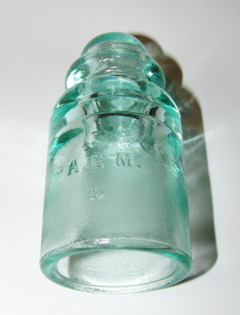
Exchange Insulators. (Left) Armstrong; (Right) Hemingray.
This aforementioned test was carried out on the CW insulator shown below. These insulators were developed for Texas and the southwestern United States as a test of its shape and leakage qualities. They were never put into extended use beyond Texas. A few appeared in Arizona and New Mexico, but they failed to result in the kind of progressive expectations the CS insulator had already proven in leakage resistance.

The Pyrex CW Insulator with the one and a half inch thimble hole.
The external shape and design of the insulator is crucial to constructing a low leakage unit. Essentially the rule is this:
The length of the path of leakage should be as great and its
cross-section as small as possible.
The Europeans developed low loss insulators of the kind illustrated at the headpiece of this article, with attendant long skirts and deep wire grooves featured at the very top of the unit. The distance between the conductor, tie wire and the exposure to the steel (predominant in Europe and Asia) pin was significant. One can fight the foe of leakage by just making a long insulator. This longer path–which also furnishes a wider area for contaminants to cling–can be eliminated if you make the insulator decreasing the insulator’s diameter.
Congratulations! You’ve made a low leakage insulator. However, you’ve still got a problem: go back to the drawing board, because you’ve now created an insulator with lower mechanical strength.
An AT&T test insulator developed by Bell Labs, similar to the Australian open wire tempered example below, was subjected to many weather extremes. One issue, too, was the need for an unconventional and longer steel or wooden pin–which added further expense to the unit’s possible practical use. Are you going to re-build hundreds of miles of open wire with new pins and insulators, plus the labor expenses to do so?
I think not.
There is another alternative to consider in our development of a new insulator with low leakage. That is we can make the insulator shape smooth and as close to vertical as possible. We want the insulator surface to be extremely smooth, to eliminate the adhesion of water, dust or other particulates to the surface.
Furthermore, if you want to build a stronger, and maintain a longer surface protected from external weather, temperature and particulates, you can bend in the inside to flare in a “petticoat” fashion.
Telephone insulators were developed with this “DP” or Double Petticoat, for these reasons. While electric power transmission and distribution insulators evolved to have two, three and sometimes four, of these petticoats, communications insulators never hatched more “sheds” or petticoats beyond two.

Two of these CW-type insulators were used in tandem.
There is also the element of the crossarm or transposition bracket steel below the insulator base. When rain hits the crossarm, moisture is bounced up underneath the insulator and into areas which are best kept dry, so as to prevent further leakage currents.
Some consideration was given to flaring the inside of the insulator, but these recessess on testing, proved to be detrimental. Water would seep into these recessess and then would not dry as quickly as on the outer surface of the insulator.
Additionally, water would pool in these deep areas, causing the insulator to maintain moisture longer. This was not the answer.
However, one could experiment with the pin of the insulator itself.
One of the interesting effects of water on tempered, versus soda lime, glass insulators, was that borocilicate glass tended to create “islands” of water. The drops adhered to the surface, with areas of dryness in between them. Soda lime glass insulators tended to shed, or cause rain to run in streams across and down the insulator surface. This peculiar characteristic was not lost on insulator designers.
Because these “islands” of water–or because they contained contaminants to make them conductive to electric currents–were separated by dry areas, leakage currents could not be continuous. It was found that this characteristic was typical of new tempered glass, but over time this idiosyncracy of the tempered insulator was altered. Tests found that such changes from “islands” to “streams” of water over the insulator surface would change on a new insulator within weeks of time duration.

Above is a 1926 Ohio Brass Catalogue page detailing the double groove wet process Pony insulator available through their “jobbers”.
In this case, one might consider that the design is more important than the material from which the insulator is made. Essentially surface matter will evidence more change in the leakage currents over time and contaminants would become the paramount issue in insulator design.
Alkali or soda lime glass, is more porous and while the surface from our own eyes appears smooth, considerable inconsistencies appear in this glass when under the microscope. Indeed, when compared to tempered glass, the surface is marked by rough edges and brittle construction. This is due to the uneven cooling of the outside surface to the inside glass. The chemical stability of the soda lime glass is simply not the quality of the borocilicate type. Tempered glass, because cooling is controlled from inside out and outside in, is mechanically harder and has a more stable surface with fewer dimples and inconsistencies.
 How different shapes of insulators correspond to wet weather leakage losses. The vertical axis represents the microhms per loop mile of leakage. The bottom numbers correlate to the frequency in kHZ.
“Does the color of a glass insulator relate to any technical consideration as to their placement on open wire lines?” I’ve been asked.
No. Whatever insulator was designed to be introduced to a particular voice frequency line, pony, exchange, toll or DP, could be of any color. Green, which fortuitously was the result of chemical issues with iron oxide compounds in glass, blended well with the surrounding landscape. It was indeed, pleasant to look at over pole after pole after pole. However, the green color was mainly the result of an accident: bottlemakers’ blending of various glass mixtures and their inherent contaminants resulting in this beautiful result.
Interestingly, the absence of iron oxide, results in a purer glass, and a substantially clear “white” insulator. Transparent glass insulators began to appear in the 1920s as the result of insect tests. Or more specifically: insects and spiders.
Spiders are not insects, but hunted them as prey. To make their homes, it was found these arachnids favored the undersides of dark green insulators. Not only did it furnish protection from the elements, but spiders prefer dark spaces for nesting and bearing young.
Tests performed on various types of insulators–dark and transparent–proved that insulators’ opaque qualities were significantly important in the insulator’s efficiency.
Possibly one of the reasons that porcelain was not the choice of North American communications companies’ open wire insulation, was borne out in the fact that where porcelain insulators were used in Europe by telcom companies there, the insect or spider liability reduced the insulators’ efficiency considerably over a few years. The more transparent the material, the less likely the insulator was to become a nest for spiders, then dust, other foreign material and high leakage over time.
Insulators over time are subjected to energy flow which dissipates in incremental amounts in the form of heat. This is variable, since weather conditions and climate also have an impact. However, this tendency of the electric field to impart this condition is called dielectric absorption.
Dielectric absorption is important because over the length of a line, and the pairs equally spaced throughout the crossarm configuration, these losses become quite important. In voice frequency lines, this is less of a problem; in high frequency carrier systems, it is a fundamental issue of design.
In high frequency, this dielectric absorption increases markedly. The higher the frequency on the upper end of “C,” “J,” or “O,” AT&T Carrier systems or Lenkurt and other important carrier technologies, the more loss can be expected over distance.
Corning Pyrex introduced the new carrier CS insulator in the late 1920s. The original tempered insulator contained as few contaminants in the glass as the technology of the time would permit. It was a solid, strong, low loss, and mechanically stable creation.
However, it was found in this type of glass–borocilicate–or tempered, that these “islands” of conductivity would arise during rain storms. Furthermore, even with mild variations in temperature which produced morning dew on the surfaces of these insulators, it introduced similar problems, until the moisture evaporated, or the snow sublimated.
Pyrex introduced the bi-metallic salt surface film to their insulators so as to combat this problem, both their communications insulators and also to their larger cousins, the electric power variety. It was with the electric power variety–particularly large ten-inch suspensions and large diameter pin types, that its use was most publicly denounced.
For communications industry insulators, introducing the metalic salt film to the surface of the insulator improved its dielectric absorption significantly where high frequencies were involved. An increase in capacitance between the wire, tie wire and pin by coating the outside of the insulator–namely the top and groove and skirt–would be invariably greater than a “wet” insulator. So, Pyrex introduced a film coated CS insulator, recommending that the steel CS pin pairs be bonded below the crossarm by a 109 line wire to each pair pin washer and nut, to eliminate these problems.
Communications companies tested non-film vs. metallic film coated insulators together. When transparent soda lime insulators were used on a three channel carrier system, such as Type “C,” the leakage compared to the wetted insulator was only ten percent. When a similar test was done with a borocilicate “tempered” clear insulator, the result was four percent leakage compared to the moistened insulator.
Insulator pins made of steel had far greater losses for capacitance than did the wooden locust pins. However, it was a sacrifice of mechanical strength for this lessened effect. High grade glass and higher seemed to have less effect, so this demonstrated to insulator designers–especially for carrier systems–that this was a negligible effect. High grade glass of the Pyrex, or tempered variety, was sufficient to pass muster and achieve a high quality for carrier demands.
Metal-coated insulators achieved a good reputation in the telecom industry. However, that same practice gave tears when introduced in the electric power transmission industries, when Pyrex introduced their ten-inch suspension insulators and wide diameter one-piece 35-kv pin insulators. Here, the issue was arcing and radio (RIV) interference voltage.
Insulators are inserted on pins, pins dropped into holes drilled for crossarm attachment, for communications’ open wire toll-level lines. Because the wood fiber of the crossarm–cut and treated from conifer tree growth–is naturally an insulator, this achieves a higher quality, low loss configuration in general.
The displaced current is carried from the linewire or tie-wire down the surface of the insulator to the pin, down the pin to the contact where the pin shoulder and crossarm meet.
There are losses in the crossarm, although not particularly great in dry weather. To determine electrical losses in crossarms, it is important to combine the crossarm’s electrical equivalent with the insulator capacitance. In wet weather, the increase in insulator capacitance tends to increase losses, as we’ve noted previously. A large decrease in the crossarm impedance resulting from raintends to decrease the losses oddly enough. Since these effects oppose each other, the crossarm loss tends to be small in wet weather.
Leakage currents in wet weather are the most important problem in consideration of designing high frequency open wire carrier systems. Much engineering has been done on this topic and many tests performed to examine how the issue might be resolved. Here is a succinct electrical diagram of the typical high frequency toll insulator:
Let’s examine our example, the CS tempered glass insulator:
We’ll cover the insulator with driving rain;
Let’s divide the sections of the insulator into spaces;
Place a small displacement current at the arm, which seeks to flow from the arm to the steel pin;
The insulator itself is a dielectric and cannot conduct electricity; however, the outside insulator area is spotted with moisture;
This thin layer of water offers some resistance to the current, but will carry it to the groove, wire and tie wire, producing a small amount of heat
The wire-to-pin capacitance will decrease, as we’ve noted previously, with increasing frequency when using film-coated insulators.
To improve the loss situation in the early 1930s, communications companies introduced a number of new insulators. One was the CW and the other CS. The CW never achieved notariety of any significance, but the CS was a successful introduction and achieved significant and widespread use. The CS and its evolved cousins, the CSA, CSC, were widespread throughout the United States.
In a Bell Laboratories test conducted on a working Pennsylvania lead, the three basic types of insulators were tested: DP, CW and CS. They were applied to lines using the Type “C” three-channel carrier system. In the first test they looked at the DP No. 42 Hemingray insulator. At the 30 kHZ frequency, the direct surface leakage was about five percent of the total losses. The glass’ dielectric absorption was about ten percent, and the dielectric absorption in the wooden locust pins was about twenty percent. Ten-pin ten foot fir-treated crossarms accounted for about ten percent more loss and if you included the insulator surface losses, this contributed about fifty-five percent leakage.

Two versions of the wooden cob-end pins for 1″ diameter insulators.
When the CW type insulator was tested the bonded pin thimbles shielded the wooden pins from the electric field and elminated dielectric absorption from the pins. The bonding in effect, short-circuited the crossarms, and eliminated most losses.
The direct surface leakage was about twelve percent of the total losses, the borocilicate or tempered glass accounted for a minimal five percent loss, and the surface losses contributed about eighty percent of the total. Tempered glass in the CW counteracts the increase in larger pin thimble construction which in turn increased capacitance.
One of the reasons the CW insulator fell out of favor beyond its limited application in Texas and a few locations in New Mexico and Arizona, was the superiority of the CS over it, in extended field testing.
Attenuation, or losses, affects the audible speech heard by the receiver, and is a major problem for telephone engineers. Because in the early days, open wire was a significant percentage of physical outside plant, these losses required considerable engineering. It was well known that losses in transmission over toll lines of signifant distance were from several main sources:
resistance of the conductors, wires and tie wires in series
variable factors such as leakage conductance between the wire pairs and other pairs which might vary greatly depending upon weather conditions.
Weather could play such a dynamic role that within 200 feet, in one test, it was required to transpose the pair to eliminate significant attenuation. Instead of using No. 42 insulators and replacing them on systems using 165-mil copper conductors with CS insulators, the attenuation in wet weather was cut by seventy-five percent of the previous DP values.
In the Dust Bowl days, the stricken plains states suffered greatly from the drought which did not alieviate until the early 1940s. These severe climatological conditions impacted telephone service, which at that time included carrier and voice frequency metallic circuits throughout North & and South Dakota, Nebraska, Kansas, Colorado, Oklahoma, Texas and parts of Iowa and Missouri.
Induced voltages from the blowing wind and dust created static problems which were much pronounced on insulators and other outside plant facilities. Because these fine particulate matter created and acumulated an electric charge as they passed through the air, radio noise was heard as popping and loud static. In telephone systems, these particulates infiltrated central offices and repeater huts, causing much interference. Switchboard operators experienced some rude shocks from these inductive charges when plugging in lines from rural areas.
What is most interesting about this phenomena was that it was so widespread, that at times, iron and steel fences, antennae and steel clothes line wire was glowing occasionally. Grounding phantom circuits was done to eliminate much of the problem. Furhtermore, some independent telephone companies used a 2500-ohm ringer with a grounded center circuit introduced, so as to “bridge” the problem.
Another issue experienced by telephone engineers was the problem of dirty contacts on relays and repeaters. Cleaning had to be constant and relay covers were taped shut to void the problem of shorts.
Insulator Pins

A pin in use by railroads and transportation companies in the 1970s which avoided the wooden cob’s sticking within the insulator pin hole when insulators were replaced. Lead thimble is 1″ diameter.
Insulator Pins came in nine types:
Steel with wooden locust cobs – one inch style diameters:
Type “A” which was used on steel and iron brackets, which could accomodate standard Toll, Double Petticoat (DP) and Exchanage insulators: 5/8-inch sizes for use on severe stress break irons and corners. They were also used on the CS Transposition Drop Bracket (reinforced style).
By coating the insulator with bi-metallic salts, as Corning did with their Pyrex-Brand insulators of all types, decreased significantly the weather conductance creating high resistance factors. This coating increased the resistance over ten times that of a normal insulator–and this is why the chemical application found such success in the communications industry.
However, we’ve not touched on the inner petticoat or flare of the insulator at its base. When you increase the resistance on the outside of the insulator, the losses on the inside of the insulator skirt increase markedly
The Type “B” steel pin long shank with shoulder. The 5/8-inch pin was used for large conductor sizes, such as 128, 165 mil, (or larger) for example. They were predominant for use on many railway systems, because it afforded strength for higher voltage A.C. signal circuits. The civilian telephone companies used these most often to support conductor configurations on corners (either mild: 5-15-degree angles) or severe (45-degree or greater) and double buck-arm deadend structures. Additionally, where a long crossing had to be made, these pins offered extra strength, such as dipping down steep canyons or up the opposing sides.
Wood is a fibrous material with natural insulating abilities. Tests on wooden pins, even when wet, evidenced good reliability although leakage of currents between pairs did increase markedly.


N.E.L.A. low voltage power distribution pin on left and standard telecom pin on right. Both 1-inch diameter thread sizes.

Steel pin with wooden cob used by Mountain States Telephone among others as well as wide use by railway companies. One-inch thimble size, locust wood cob.
This is the “CS” steel pin above. It was introduced in the late 1920s for carrier systems and the governed the use of the “CS” tempered glass insulator. In tests, two of these steel CS pins were tried: the first was a conventional height of insulator base to crossarm, as akin to the traditional wooden pin, and the second was an elevated CS steel pin with double the distance between the crossarm surface and the insulator base. This reduced the effects of splashing by water into the interior of the insulator.
Additionally a steel “baffle” was instituted on the pin to close any further openings to water, dust and temperature variation. This was a second “shoulder” immediately around the base of the screw spiral. You will note this on the example below. Some further tests used a rubber gromet inserted on the base of the top baffle so that when the insulator was screwed upon the pin, the contact between the glass and baffle was not only further insulated, but was nearly impervious to outside contaminants. It also was found to be a shield against glass fracture where otherwise the cold surface of the steel met directly with the warming glass insulator.
Later, REA would require the use of a plastic bushing to be inserted on steel pins so that this inexpensive moderator would perform the same purpose, only less expensively.

CS pin with shoulder and 1-inch pin hole adapter washers.

Can’t place poles in rock? Strike insulator bracket spike into tree! From Deadwood, South Dakota Mining District.
The standard AT&T wooden pin, by which nearly all commercial communications companies used as their standard, was the the locust 8-inch style. These could handle common supporting tasks with nearly all diameters of communications conductor. Additionally, they could support DP, Toll, Exchange and Pony glassware. By inserting the pin up to the shoulder in the drilled crossarm hole and then driving a single six penny nail two inches below the roof of the arm (on the front side), these pins could be securely held without contorting or spinning.

Rural exchange carrier galvanized single pair bracket. Acceptable for REA telephone borrowers.

REA-acceptable for borrowers single pair galvanized steel bracket with O-Carrier 4-inch tramp bracket.
“C” type dead-end insulators for open-wire construction. To far right: smallest guy strain insulator ever used for telcos.

Light duty C-type dead-end clevis for telephone open wire.

Heavy duty C-type dead-end for the stress experienced by railway’s heavier conductor sizes.

Typical application of the C-Type Dead-end clevis, pin, cotterkey and wet process porcelain spool insulator with carriage bolt through pole. Hardware on the reverse side is a guy strand bracket with 5/8-inch through bolt, washer and nut.
The “C” type dead-end originated when dead-ending pairs on crossarms and wooden brackets exceeded the ability of wood to hold its strength over the long term. Double arming, with the installation of two pins for each line wire and wrapping them in a figure eight pattern lessened the stress on the arm, however it was not suitable for a multitude of other occasions and needs. For example, to dead-end on a sloping ground, at the bottom of a steep grade or top of a steep grade, caused problems.
The most important problem was simply the rot issue. Pins–even those made of Locust wood, largely impervious to rot in the long term–did not withstand stress well. Additionally, when water and moisture entered the pin hole at the wooden pin’s shoulder, meant that deterioration might be hidden and entire parts of the inner arm might be rotted out.
With a C-type dead-end bracket, whose advantages had been long established in the electric power field with secondary clevis-type brackets, rot was less likely because of the attachment on a vertical plane, instead of the top arm placement as with pin-type dead-ends. Furthermore, the steel required a 1/4″ carriage bolt, which locked into the back of the “C” unit and then was held captive with a bolt and washer on the opposing side of the arm.
Important, too, was the loosely fitting porcelain spool insulator, which could assume a number of positions and rotated on the clevis assembly bolt, withstanding strain much better than a pin. Double dead-ends could easily be created at storm structures or at locations where pins would be unable to stand the strain of long river crossings from H-fixture to an H-fixture on the opposing bank of the river.
Porcelain spools tended to be stronger and more flash-arc resistant than glass insulators screwed upon pins. They were easy to replace with a cotter key removal and insertion of a new insulator spool on the clevis. In their positions vertically assembled in banks on an arm, one could easily field modify a BDE arm for carrier crossarm transposition pair measurement demands. Also, in dead-ending a single pair for a bracket lead, a vertical dead-end was possible and no two pin crossarm or doubling of wooden brackets was necessary.

Left to right: Reinforced ARA dead end, two self-locking Sagger-types and far right: Bell & Independent style. Foreground: mini guy strain unit used for early railway and indepedent telco use. Some incorporated a special clevis.

Hardware to utilize guy strain insulators as dead-ends on this UPRR 2.4-kV Delta a.c. CTC power circuit. Underslung disconnect switches complete the circuit arrangement with jumpers.

The RACO DEAD END unit for use in American Railway Association/Communications Section Specified systems. Note uniquely formed oval eye bracket. Insulator was secured in position by conductor tension. From Panhandle & Western Railway (BNSF).

Another view of the RACO bracket. The insulator is held captive within the eye bolt. This bracket is from the 1940s.

Early railway-style “Break Iron” bracket with wooden insulator thimble cobs and Type B wooden bushing (for crossarms drilled for one inch locust wooden pins).

Railroad style double dead-end assembly for open wire. The spools are firmly anchored by bracket and do not revolve in place as with the telco “C-Type dead end clevis.

Joslyn railroad-style crossarm support single wire dead-end spool shackle. Mfg’d after 1966.

CS, CSA, CSC & TS low leakage, high frequency carrier borocilicate glass insulators.

From left to right: tempered glass insulators introduced in the late 1920s to 1950s for high frequency three- and twelve-channel high frequency carrier. Last insulator on right superceeded previous designs and was meant for 16-channel carrier (1955).

Case span and crossarm-mounted specialty insulators for the point-type bracket. Glass on left and fiberglass spool on right.
Transposition Brackets
Various “Tramp” Brackets and Their Applications

The standard “S Transposition” drop bracket. The bracket was sold with the carriage bolt above only. Pins sold separately.

The reinforced (line angle) “CS Transposition” drop bracket. There was also a toughened “P” companion phantom bracket of the same reinforced construction available to the outside plant engineer.


Two views of the 2-piece “P” Phantom Transposition Bracket (earliest style).

Lift bracket in use by Chicago-Northwestern Railway Company. Used in conjunction with double armed pole.

Heavy duty steel Bell System Break-Iron tramp brackets for 6-, 8-, and 12-inch point-type transpositions. Photo below illustrates how they can be made to be either “right” or “left” twist.

Bell, GTE (heavy) type break-irons used for point-type transpositioning. Typical installation. Extra hole next to the attachment bolt was for lag screw to stabilize unit.

6-inch single piece Bell System Point-type Transposition Bracket.

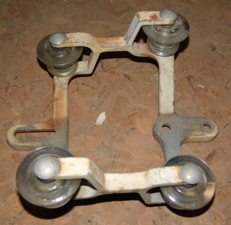
The “Point Type Phantom Bracket” which occupied four pin positions on a standard 10A arm.
The “Point-type Phantom” Bracket is an interesting test of the “point-type” transposition taken to its furthest development. In my researches, over the last 50 years, I have never found a single article devoted to this uniquely designed and applied bracket in the literature. Furthermore, there was only one major (and minor) open wire lead using this particular device. From this, I deduce it was a first and last attempt at such a transposition element.
The Point-type Phantom Bracket was used in the late 1940s on only one line in the United States which I recall: the Kansas City, MO to Council Bluffs, IA lead. As a kid in the early and mid-1960s, I could recall seeing thousands of these unique brackets–they were large, taking up four pin positions on a standard 10A arm–along U. S. 275 near Sidney, Iowa (north and south of that location). When the lines came down in late 1968, they were made available to this project.
Anyone out in the telephone/communications community who remembers these on that particular lead–or some applied to systems in their diverse areas of the United States–please contact us. I can only come to one conclusion about this particular unit’s use: a test by AT&T Long Lines to achieve a more proficient transposition design than the regular phantom “Butterfly” bracket. Indeed, it was made perfectly clear in the closing days of open wire, that the CP bracket was essentially “ineffective” at creating a useful working transposition. Hundreds of thousands of these Phantom Transposition Brackets were employed throughout the United States and it is amazing that they were largely . . . useless.
Perhaps this was a last strategy to develop a phantom bracket with effective merit and the result was this experiment called the “Phantom Point Type Bracket.” It would be very interesting for those of you familiar with this unique item, to contact me with more information.
These are exceedingly rare. I’ve been to 42 states in the Union and never have seen anything like it.

Detail of “Point Type Phantom Bracket” end section.

The “B Pinch Bracket” newly adopted for O-Carrier in 1955.

New bracket for O-Carrier (1955) the Four-inch Point Type Bracket.

Tandem Transposition Bracket with two CW insulators mounted on REA side arm.

Single pair Tandem Transposition was longer than break-iron brackets. Base profile depressions were not present. Bell types incorporated a slight “T” center extension for a lag screw to maintain firm alignment on arm.
Early railroad style 8-inch Western Union style Hubbard point transposition bracket. Circa 1918.

Hubbard 8-inch Point Type Bracket for railway use.
Earliest design of Case (Alcoa) aluminum crossarm mounted 6-inch point bracket

Case 6-inch (crossarm-mounted) point-type bracket used by both railways and commercial telcos. Later version (1940-1950s).

Two lightweight break irons secured by stabilizing hardware. Point type REA accepted (1952) units from United Telephone (Texas). Bottom side end.
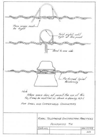
Insulator Ties & Line Wire Reinforcements
The attachment of the line wire to pin-type insulator or dead-end spool bracket was of paramount importance for several reasons. First, the attachment needed to be rigid, but semi-flexible, so as to account for changes in conductor shrinkage and expansion during the different seasons. Additionally, it had to be a nearly permanent means to support the conductor so that proper sag in the span could be accomplished, yet strong enough to restrain the conductor from aeolian and other vibration problems . . . birds, small branches, kids who liked to rock the pole back and forth to watch the wires tingle together . . . Thirdly, there were many types of ties. Some were wedded to “preformed” or standard-length manufactured “stiffeners” which prevented wire fatigue where wind was a frequently encountered liability in some districts.
The types of ties were as simple as the standard “Western Union Horseshoe” to elaborate styles which incorporated pig tails and multiple wraps such as at double crossarm angles and pin-type crossarm or bracket dead-end arrangements.
We will review a few of those particular to the communications industry below:

REA acceptable to borrowers’ dead-end preformed ties.


The Alcan Tie
by Dr. Don Martin
The Alcan Tie was developed to withstand the great stresses imposed by arctic conditions on wires. Intense cold makes metal contract intensely, and ice fogs can balloon 1/8-inch wires to 1-foot-thick sausages weighing many pounds per yard and capable of breaking wire with a tensile strength of 1,800 pounds. One task we enjoyed at Tok was walking the lines on snowshoes carrying pick handles after we had had an ice fog. We would go to the center of each span and throw the handles against the wires to break the ice loose, ducking the chunks as they fell. We did this before the ice had grown larger than 3 inches, so the chunks were not lethal, only painful if you did not duck well: it was a game. With this sort of ice load, bending soft tie wire around the insulator and spiralling the ends in each direction down the line just was not enough to hold, but the Alcan Tie was reputed to withstand the cutting of the line itself: the parts attached to the insulators would remain on them with very little shift. If you cut all the lines, of course, the pole itself would soon be on the ground, but that is another problem entirely.
The Alcan Tie requires special augmentation in the form of rigid, pre-formed spirals, made of steel-cored, copper-clad wire of a slightly heavier guage than the line itself; the spirals were about a foot long and came in bundles of 50 or so. They threw excellently well from the back of a speeding line truck, screwing themselves by as much as 4 inches into billboards when striking the plywood properly. For the intended use, you wrapped one around the line alongside the insulator, starting at the center of the spiral and turning both its ends in the appropriate (and opposite) directions. With a length of regular tie wire (pure copper and soft) you laid on two turns in each direction at the middle, took the ends around the insulator and brought them together, over and under the line, on top of the spiral. Then you would get a good grip on the tie wire ends with your pliers (most of us used end-cutting nippers for this), pull them tight, and twist them into a pigtail. The pigtail was flattened down the skirt of the insulator and snipped off even with the hem.